Complex Nonlinearities Epsiode 2: Harmonic Exciter
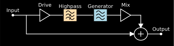
In this article I’d like to examine a nonlinear architecture used by old aural exciter effects to generate harmonics for a signal. The general signal flow looks something like this:

For the programmers out there, this article can also be viewed as a Jupyter Notebook: https://ccrma.stanford.edu/~jatin/ComplexNonlinearities/Exciter.html
Implementation: Level Detector
For the level detector part of this system, you have a lot of options. For instance you could start with a level detection scheme similar to one you might use in a compressor or gate effect, with parameterized attack and release characteristics (for more information, see here). In this implementation, I will use a somewhat simpler scheme: a rectifying nonlinearity followed by a lowpass filter.
Rectifying Nonlinearity
The idea of a rectifying nonlinearity is to take a signal that has both positive and negative values, and and transform it into one that contains only positive values. Here I’ll examine three common rectifying nonlinearities:
- Ideal Full Wave Rectifier: The idea here is that the positive half of the waveform is left unchanged, while the negative half is flipped to be positive. Mathematically this is the same as the absolute value operation.
- Ideal Half Wave Rectifier: Similar to the Full Wave Rectifier, the positive part of the signal is unchanged, but for the Half Wave Rectifier, the negative part of the waveform is set to zero.
- Schockley Diode: A diode is a circuit element that is often used in rectifying circuits. For our purposes, we can think of it as a less ideal Half Wave Rectifier. For a mathematical treatment of Schockley Diodes, see here.
Below, you can see the static curves and sine wave responses for three types of rectifying nonlinearities.


Lowpass Filter
The lowpass filter used in a level detector typically has a pretty low cutoff frequency. I often use a cutoff frequency somewhere around 10 Hz. I won’t discuss the technicalities of creating a lowpass filter here, but more information can be found in Julius Smith’s Introduction to Digital Filters.
Level Detector Example
Now let’s take a look at how the various level detectors handle a typical audio signal. Below we see the response of three level detectors, each using a different rectifying nonlinearity, and each using a first-order lowpass filter with a cutoff frequency at 10 Hz.

The most obvious result is that the diode nonlinearity leads to a much less stable level detector. In order to make the diode match better with the other detectors we could use a more strict lowpass filter, but the less stable level detector might also contribute to a more interesting overall nonlinearity. You also may notice that the peaks of the level detector outputs are a little bit delayed compared to the input signal. Again, this could be fixed by adjusting our lowpass filters, but in the context of our overall nonlinearity a slightly delayed level detection can lead to some interesting effects, in this case the distortion of our effect will seem to “smooth out” any incoming transients.
Implementation: Nonlinearity
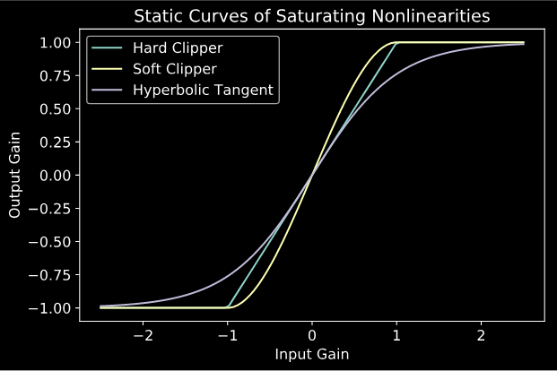
For the nonlinearity used in an exciter, it is typical to use a saturating nonlinearity: that’s a nonlinearity that approaches constant output as the input gain grows large. I’ll show three options here (hard clipper, soft clipper, hyperbolic tangent), but feel free to experiment and try your own things!
Putting It All Together
Now let’s go ahead and connect these elements as shown by the diagram above. Below I’ll show the static curve and harmonic response for a 100 Hz sine wave, for an exciter with a diode rectifier, 10 Hz Lowpass Filter, and hyperbolic tangent nonlinearity.


The static curve for the exciting nonlinearity has an interesting width to it, since the increasing and decreasing parts of the waveform have slightly different characteristics. We can see the effects of this asymettry in the harmonic response, in the prescence of the even harmonics in the signal. Perceptually, the even harmonics help the exciting nonlinearity to sound “smooth” compared to a traditional saturating nonlinearity. Additionally, the “speed” of the level detector, as determined by our lowpass filter, can add a cool “ramping” effect to the transients of the sound.
Anti-Aliasing
Doing a complete analysis of the harmonic response for a nonlinearity as complex as this would be quite complex, the interested reader is encouraged to see Chapter 2 of a recent dissertation by Francois Germain. Through my own more empirical testing, I’ve found that oversampling by 8x is sufficient to eliminate aliasing artifacts down to ~100 dB.
Examples
To demonstrate this nonlinearity in a more realistic scenario, I have developed an audio plugin (VST, AU) that implements all of the options discussed above, as well as a variable filter frequency for the level detector, and drive level for the exciter overall. The source code for the plugin is available on GitHub. A video demo can be seen below.
Finally, I’d like to take a moment to show how this type of nonlinearity is often used in the context of an aural exciter. Exciter circuits often refer to the nonlinear section we have analyzed here as the “Generator”, since it generates higher harmonics of the input signal. The general architecture can be seen below:
Finally
Thanks for reading through another episode of this recurring series! I hope this article has helped inspire some ideas for cool sounds that you can make with your own DSP. For next time, I’m hoping to have a generalized, non-physical model of one of the coolest and most complex nonlinearities out there: hysteresis.