Complex Nonlinearities Episode 5: Nonlinear Feedback Filters
In last week’s article, we discussed a method for enhancing a standard framework for digital filters by adding nonlinear elements. In today’s article we’ll be looking at another, very similar method, with a pretty cool final sound.
Developing the Structure
Just like last time, we’ll be starting the with a Biquad Filter, in the “Transposed Direct Form II”. If these words don’t mean anything to you, please take a minute to read through the beginning of the previous article, where we discuss these concepts in more detail. You may recall that previously we added nonlinear elements just before each delay element, as shown below.


Today we’re going to try something a little bit different, and look at what happens if we choose instead to add our nonlinear elements into the feedback paths of the filters. It is well known that filter feedback contributes to filter resonance, so we’ll expect that the nonlinear modifications will affect the filter resonance.
Frequency Response
Like last time, let’s now take a look at what happens to the frequency response of the filter when we change the input gain. For this example, we’ll use a lowpass filter with a cutoff at 1 kHz, a Q of 10, and tanh clippers for our nonlinear elements.

From the above plot, it seems pretty obvious that as the gain of the input signal increases, the resonant frequency of the filter seems to shift as well. Vadim Zavalishin describes a similar effect that occurs when adding nonlinear elements to the feedback paths of a ladder filter, and he has a useful way of thinking about this phenomenon: “as audio-rate modulation of the cutoff (frequency)”[1]. The result of this modulation will give some pretty neat sounds which we’ll hear more about below.
[1] The Art of Virtual Analog Filter Design (rev. 2.1.0), Vadim Zavalishin
Pole Analysis
I’m going take a small leap here, and try to do a little bit of math to show why the nonlinear filter reacts in this way. If the math isn’t making much sense, feel free to skip this section. First, we need to define a couple of things. If you’d like to see this derivation given with a more technical treatment, please check out this paper.
Filter Poles
The resonant frequencies of a filter are defined by it’s “poles”. These poles are complex values that show where the feedback of the filter reaches a maximum. To find the poles for a linear filter, we can use the quadratic formula on the a coefficients of our filter as defined in the Direct Form.

The resonant frequencies of the filter are then defined by the “angle” of this complex number, which can be found using
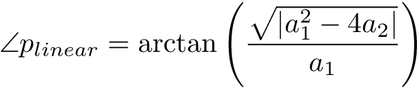
A larger pole angle corresponds to a higher cutoff frequency, and a smaller pole angle corresponds to a lower cutoff frequency.
Nonlinear Gain
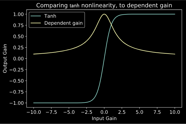
The next thing to consider is that a nonlinear function can also be written as a dependent gain. For example, the dependent gain for the tanh nonlinearity looks like this:
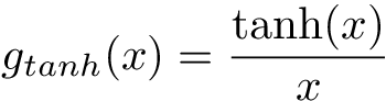
For the tanh nonlinearity (as with many nonlinearities), the dependent gain will always be in between 0 and 1, and as the input increases, the gain decreases to zero.
What happens to the poles?
Now for the million dollar question: what happens to the poles of the filter when we add the nonlinear elements? The basic answer is that the aa coefficients are multiplied by the dependent gain values. Then the new pole locations can be described by

And then the new pole angles become:

I won’t go through the math here in gory detail, but using the property that the gain goes to zero as x grows large, we can show that the poles shift to larger angles for larger input gain.This movement of the poles explains why the cutoff frequency of the filter changes with the input gain.
Anti-Aliasing
As usual, it’s worth taking a minute to discuss that harmonic response of this system, and think about any aliasing problems we might have. To get a sense of that we’re dealing with, I’ve taken the example filter from earlier (cutoff = 1 kHz, Q = 10, nonlinearity = tanh), and plotted it’s harmonic response for a 100 Hz, and a 2kHz sine wave.


So we get kind of an interesting response! Along with a larger bump around the resonant frequency of the filter, we see a few odd harmonics generated for each input. It also seems like the filter does a little bit of filtering of its own generated harmonics, which is pretty interesting. In my own rather subjective testing, I haven’t had much of an audible issue with aliasing artifacts, except for filters with very high resonance above 10 kHz, which sound pretty annoying anyway. Just to be safe, I like to use 8x oversampling, which typically mitigates any aliasing artifacts down to ~90 dB.
Examples
Once again, please check out an implementation of this nonlinear feedback filter as an audio plugin on GitHub. There’s also a video demo available on YouTube (see below). I was really surprised by how neat this filter sounded. The sort of “sweeping” effect of the moving pole is really unique, and I’m excited to experiment with this form a little bit more.
Finally…
Thanks once again, for reading through another episode of this series. I’d love to hear any uses you guys find for nonlinear filters of this sort, as well as where the inspiration from this article may lead you. Maybe there are other filter forms that sound even cooler under nonlinear feedback conditions like this!
For next time, we’ll be discussing one of the most unique sonically interesting musical nonlinearities: wavefolding.